- 28
- Feb
Transformer manufacturing machine- Variable Pressure Vacuum Drying
|
|
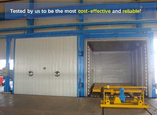
Variable Pressure Vacuum DryingProvide a set of pressure-variable vacuum drying equipment, horizontal 4000mm(L)×3000mm(W)×3000mm(H)square tank, fully automatic computer control, used for drying transformers of 35KV and below. |
Description
According to the requirements of the user, the equipment is based on the vacuum drying principle of vacuum processing and vacuum equipment design and production specifications, combined with our long-term experience in transformer production and accumulation, mainly used for drying the body of oil-immersed transformers, amorphous alloy transformer mutual inductor and capacitor . During the drying process, the equipment continuously changes the pressure inside the drying tank to make the product heat up evenly, and can eliminate the evaporation water in the tank in time to prevent the iron core from rusting. Because the drying adopts the step-by-step method, the product is less deformed and the drying is more thorough. . Because the structure and process of the device are reasonable, the drying time is reduced by about 30% to 45% compared with the conventional vacuum drying. It is a equipment with reliable performance, high efficiency and energy saving.
According to the requirements of your company, the following technical solutions are proposed to provide the variable pressure processing (30KV and 10KV two options) for the drying of electrical products for transformers of 33KV and below oil-immersed power transformers. For further consultation between the two parties.
Tech Data
5.1.Vacuum drying tank system
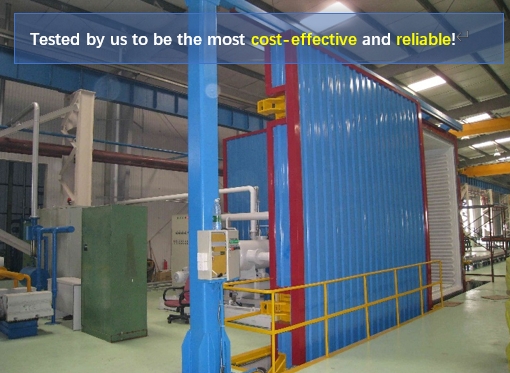
5.1.1.Drying tank size:4000mm×3000mm×3000mm (length×width×height), horizontal type, effective height means the height from the lower surface of the tank to the inner wall of the tank top is 3000mm. The drying tank adopts single-door method, the tank door is electrically moved sideways. Each set of doors is locked by four sets of air cylinders.
5.1.2.Ultimate vacuum ≤ 30Pa (no load, cold);
Leakage rate ≤500Pa·L/S (no load, cold).
5.1.3.The tank is heated by the coil heater. It has four sides (lower, left, right, and rear). The heat transfer oil is used as the heat transfer medium. The heat transfer oil is connected in parallel. The hot oil inlet is as close as possible to the tank door position. There are manual adjustment valves for each channel in the import, and four channels are connected in parallel. The heating coil area meets the process requirements of the variable pressure process. The heating control is controlled by the time proportional. The coil is welded by argon arc in the curved part. Welding is not allowed in the straight pipe part, and the three-walled coil is as far as possible to the bottom. Single-sided coil pressure test is 6.5 kg, the overall pressure test is 8 kg.
5.1.4.Operating temperature :135±5℃,automatic temperature control and adjustable. Four temperature sensors are arranged in the tank to measure :(1) temperature of low-pressure coil and core gap ; (2) the low-pressure coil airway temperature; (3) the high-pressure coil airway temperature; (4) the tank inner space temperature. All temperature sensors require a three-wire platinum with a resistance length of 5000mm. In addition, there is an insulation resistance measurement interface with 6 points.
5.1.5.The tank flange is made of long-life silicone rubber O-ring seal structure with high temperature resistance and transformer oil resistance.
5.1.6.The tank is insulated with rock wool (thickness 150mm). White color steel plate is armoring with blue edging, and the thickness of the color steel plate is 0.6mm.
5.1.7. After the rust is removed inside the tank, spray a 300℃ high temperature resin paint.
5.1.8.Two sets of observation window devices are arranged in the drying tank to facilitate observation of indoor conditions.
5.3.Trolley and drive unit
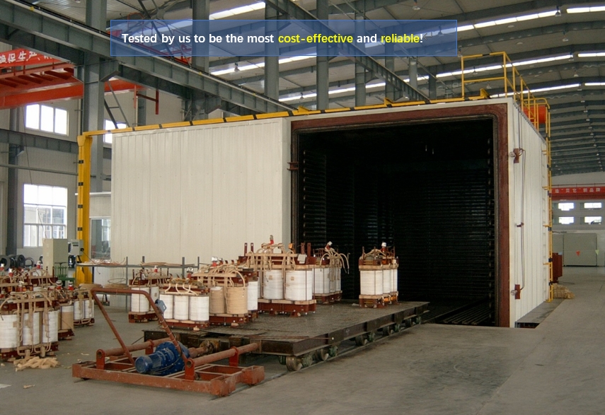
5.3.1.The working platform can bear 30T, the size of the trolley is 3700
×2700mm, and the height of the trolley is ≤500mm. Add lubricating oil to axle, add plate and air hole on site.
5.3.2.The electric traction head drags the trolley in and out of the vacuum tank. The transition track is movable and connected between the guide rail inside the tank and the guide rail outside the tank. Stable traction, no sudden stop phenomenon. (the trolley ground track shall be prefabricated by the buyer, and the seller shall provide the relevant drawings and technical requirements).
5.4.Vacuum system
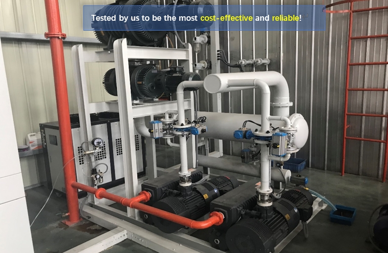
5.4.1.The vacuum system is configured as two RH0300N (Hokaido, Germany, energy saving and environmental protection), a Roots pump JRP-2000, three vacuum pumps, and the maximum pumping speed of the system is 600m3/h. The vacuum system (including pumps and valves) operates automatically in sequence.
5.4.2.Ultimate vacuum ≤ 30Pa (no load, cold);
Leakage rate ≤500Pa·L/S (no load, cold).
5.4.3.The system is equipped with high reliability vacuum variable pressure valve group, electromagnetic relief valve, manual relief valve, vacuum sensor (Leybold, Germany), vacuum pipeline and corresponding accessories. The variable pressure valve group contains DN50 pneumatic valve, DN25 electric valve, and film vacuum sensor (WIKA, the key component of the variable pressure process).
5.4.4.According to the different pressure parameters in the process, the system can reliably automatically open or close the corresponding vacuum valves and vacuum pumps under computer control.
5.4.5.The gas drawn from the tank is cooled and dehydrated by the condenser.
5.4.6.A waste gas separator is arranged, and the gas extracted by the vacuum pump is discharged to the outside of the plant through the discharge separator and the pipeline to avoid polluting the environment.
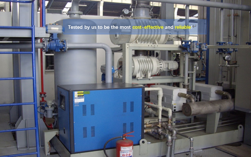
Low temperature condensation system
1.A new type of horizontal structure condenser, which quickly and effectively condenses the moisture in the tank, has an automatic drainage device that does not damage the vacuum.
2.The effective condensation area of the condenser meets the process requirements. The condensing tube material is stainless steel with a condensation area of 8m2 and withstands pressures above 6 Bar.
3.Configure a set of SIC-3W integrated low temperature chillers to provide low temperature water below 20℃ to ensure good condenser condensation effect. The water temperature value can be displayed in the terminal. The highest water temperature alarm can be set on the chiller.
Heating system
1.Drying tank heating center heating, heating power is 96kW. Conduction oil as a heat transfer medium. User provides a quantity of thermal oil to meet the heating requirements, the system is composed of heating body, high temperature oil pump, filter, temperature sensor, high temperature valve, pressure gauge, expansion box and so on.
2.Heating center automatic control, over temperature alarm, low oil level alarm of expansion tank, instrument temperature control accuracy ±0.1℃.
5.6.3.Thermal oil pipeline rock wool insulation, stainless steel sheet armor.

